However, in actual operation, some enterprises and suppliers only consider the purification efficiency and energy consumption of the system, while ignoring the safety design of the system, resulting in frequent safety accidents during the operation of the RTO system. According to the "Technical Guidelines for Air Pollution Control Engineering", "Technical Specifications for Industrial Organic Waste Gas Treatment Engineering by Regenerative Combustion Method (Draft for Comment)" and other specifications, the RTO system mainly includes polluted gas collection and transportation system, gaseous pollutant thermal combustion system, Control and safety requirements, etc. For the safety design of the RTO system, according to the requirements of the specification and combined with the engineering experience, this paper puts forward the following analysis and suggestions from three aspects: the design of the exhaust gas transmission pipeline, the main design of the RTO system (including control and safety requirements), and the debugging of the RTO system.
Exhaust Pipeline Design
01Design of conveyor system in production workshop
Products in the fine chemical industry are usually produced intermittently, and the amount of exhaust gas fluctuates greatly. If the conveying fan in the production workshop adopts fixed-frequency control, the pressure in the branch pipe section of the workshop will also change with the fluctuation of the exhaust gas amount. There is exhaust gas pressure in the branch pipe section. Risk of instability and leakage. Therefore, it is recommended to increase the pressure detection point at the front end of the conveying fan in the workshop, and set the pressure parameters according to the actual situation on site, and interlock the frequency conversion control with the conveying fan in the workshop to maintain the pressure in the branch pipe section of the workshop stable.
02 Slope and condensate discharge setting of waste gas conveying pipeline
The composition of exhaust gas in the fine chemical industry is complex and fluctuates greatly. The pre-purification of the workshop is generally equipped with a condensation and spray system, which plays the role of "eliminating valleys and leveling peaks". However, the exhaust gas after condensation and spraying contains a large amount of saturated water vapor. If the design is unreasonable, the inflection points and low points of the exhaust gas transmission pipeline will accumulate liquid and condense. In summer, the volatilization of the accumulated liquid may cause the risk of VOCs concentration exceeding the lower explosion limit. In winter, the accumulation of liquid may cause damage to the pipeline and cause the risk of exhaust gas leakage. Therefore, the waste gas conveying pipeline should design the slope of the pipeline in accordance with the requirements of the "Code for Design of Petrochemical Metal Pipeline Layout", and set up condensation discharge points at the corners and low points of the pipeline to discharge condensation regularly to avoid the occurrence of liquid accumulation in the pipeline
03 Anti-static setting of waste gas conveying pipeline
Exhaust gas transmission pipelines generally have long distances, complex pipelines, and fast gas flow rates. Static electricity will be generated in the pipeline. If a large amount of static electricity accumulates, it will cause safety accidents such as explosions. Therefore, it is recommended to use metal pipes for waste gas transmission pipelines, and according to the requirements of "Petrochemical Electrostatic Grounding Design Specifications", pipe flanges should be bridged and electrostatically grounded.
04 Pressure control design of waste gas conveying pipeline
According to the requirements of the "Technical Guidelines for Air Pollution Control Engineering", the overall exhaust gas transmission pipeline should be in a state of slight negative pressure, which can effectively avoid the risk of exhaust gas leakage and mutual gas in each pipeline. Therefore, the exhaust gas transmission pipeline needs to do the wind pressure balance calculation to ensure that the pipeline is in a slightly negative pressure state. Taking a pharmaceutical company in Jiaxing, Zhejiang as an example, the calculation steps are as follows:
1) Determine the calculation range: the outlet of each unit fan is to the inlet of the fan in front of the RTO.
2) Referring to the "Concise Ventilation Design Manual", calculate the diameter of the exhaust gas conveying pipeline according to the exhaust gas flow rate within the range of 6-14m/s flow velocity.
3) Use the wind pressure balance calculation software: PipeFlowExpert.
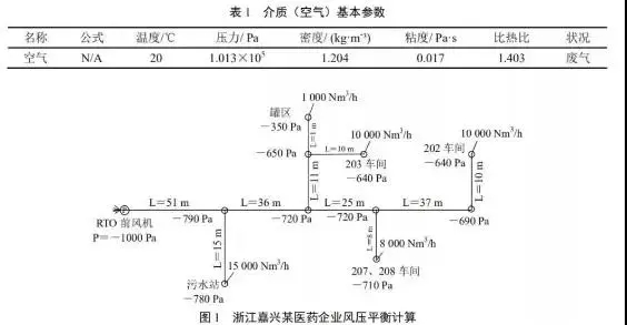
4) Select the medium as waste gas (air), and the basic parameters are shown in Table 1.
5) Selection of pipeline material, the company's pipeline material is PP, and the absolute roughness coefficient is 0.005mm.
6) Pipeline drawing, pipe length and pipe diameter input.
7) The exhaust gas flow input of each unit and the pressure of the fan in front of the RTO are to be input.
8) Obtain the calculation data of wind pressure balance in the whole plant of the enterprise, as shown in Figure 1.

It can be seen from Figure 1 that the minimum negative pressure at each node position of the enterprise is -350Pa, which is in a state of slight negative pressure, which meets the design requirements. In addition, it is recommended to set up pressure detection points at the nodes of the exhaust gas transmission pipeline and each branch pipe of the workshop, remote operation interface, and real-time monitoring to ensure the negative pressure of the node position of the exhaust gas transmission pipeline and the branch pipe of the workshop to avoid leakage and air leakage at each node position.
05PART Exhaust gas pipeline flame arrester and pressure relief settings
Through the investigation and analysis of the safety accidents of RTO furnaces of many pharmaceutical and chemical enterprises, it is found that the exhaust gas transmission pipeline is the hardest hit area for explosion accidents. Therefore, it is recommended to install flame arresters on the outlet pipelines of each production workshop to prevent the explosion accident from spreading to each production workshop. Explosion vents are set at key positions of the exhaust gas conveying pipeline to ensure that the entire system can be vented in a timely and effective manner. According to the requirements of the "Code for Fire Protection Design of Petrochemical Enterprises", RTO belongs to open flame equipment. For example, the tempering of the RTO system will cause safety accidents such as fire or explosion in the exhaust gas pipeline. Prevent and block RTO system flashback.


